Key manufacturer guidance rechecked: 31 October 2026
For owners, facilities teams and project managers reviewing device functions, circuit grouping and electrical handover.
In this guide
- The short answer: what does each device protect against?
- Overload, short circuit and residual current are different problems
- Read the markings: A, mA and kA mean different things
- Breaking capacity must match the installation
- Why the residual-current type matters with electronic loads
- Shared RCCB with MCBs or RCBOs on individual circuits?
- Existing APYS electrical-work record and trip investigation
- Repeated tripping: what should be investigated?
- What does the test button prove?
- What to request in the electrical BOQ
- Acceptance and maintenance checklist
- Frequently asked questions
- Discuss the electrical scope with APYS Projects
An MCB, an RCCB and an RCBO are not interchangeable switches. They address different fault conditions. Understanding those functions helps a client review an electrical quotation, ask useful questions about a distribution board and recognise when a tripping complaint needs proper investigation.
This guide explains the decisions for homes, offices and shared building facilities in India. It is a planning and procurement guide: circuit design, board alterations and electrical tests require competent electrical professionals using the applicable requirements and manufacturer instructions.
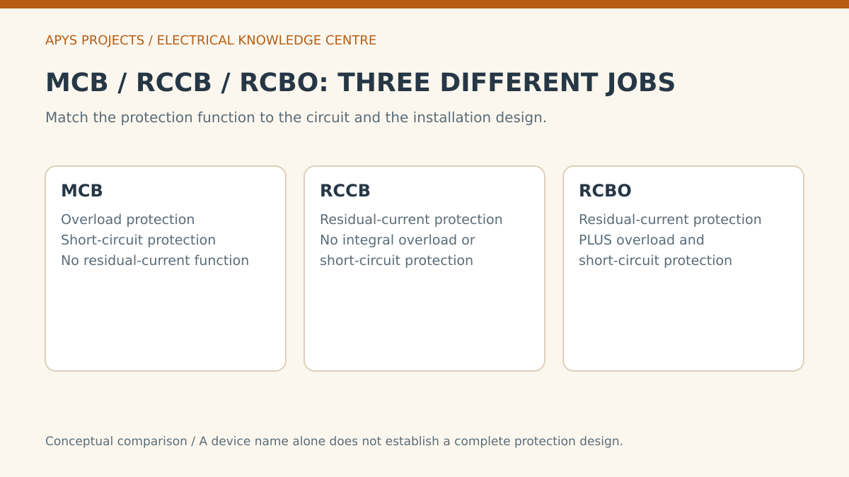
The short answer: what does each device protect against?
An MCB provides overcurrent protection against overload and short-circuit conditions. An RCCB provides residual-current protection without integral overcurrent protection. An RCBO combines residual-current and overcurrent functions. The exact performance still depends on the selected model, ratings and installation. [1][2]
| Function | MCB | RCCB | RCBO |
|---|---|---|---|
| Overload protection | Yes, within its specified characteristics | No integral overload function | Yes, within its specified characteristics |
| Short-circuit protection | Yes, subject to breaking capacity and coordination | Needs appropriate associated overcurrent protection | Yes, subject to breaking capacity and coordination |
| Residual-current protection | No | Yes, for its specified residual-current characteristics | Yes, for its specified residual-current characteristics |
| Selection question | Which cable and fault conditions must be protected? | What residual protection and associated overcurrent arrangement are required? | Which combined functions and circuit-level isolation are required? |
RCD is the broader term for residual-current protective devices. Do not assume that a shop quotation using “RCD”, “ELCB” or “earth-leakage breaker” identifies the exact product. Ask for the manufacturer’s model number and data sheet.
Overload, short circuit and residual current are different problems
An overload is excessive current through the normal circuit path, such as more sustained load than the circuit is designed to carry. A short circuit involves an unintended low-impedance connection and can produce a much larger fault current. MCB operation responds to overcurrent characteristics; it is not evidence that a residual-current protective function exists. [2]
Residual-current protection responds to an imbalance between the currents passing through its sensing arrangement. That imbalance can indicate current returning by an unintended path. The sensing and tripping technology varies between products. [7]
This distinction explains why “the MCB did not trip” is not a complete diagnosis after a shock complaint. Equally, fitting a residual-current device does not eliminate every shock scenario or replace sound insulation, earthing, bonding and a suitable installation design.
Read the markings: A, mA and kA mean different things
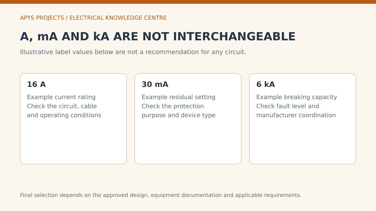
A device may carry several electrical ratings. They are not alternative ways to describe the same capacity:
- Ampere rating, A: an operating-current characteristic to coordinate with the circuit and equipment.
- Residual operating current, mA: a residual-current characteristic associated with the protective purpose and device.
- Short-circuit breaking capacity, kA: a fault-interruption characteristic to assess at the installation point under the relevant product standard.
The illustration uses 16 A, 30 mA and 6 kA only to show the units. It does not recommend that combination for a socket, air-conditioner or any other load. An RCCB with a stated ampere rating does not become an overload protective device because that number is printed on it. [1][4]
Ask the designer to record the relevant voltage, poles, residual-current type, overcurrent characteristic and environmental conditions. A purchase description containing only “32 A breaker” leaves important choices unspecified.
Breaking capacity must match the installation
Fault current depends on the supply and the path to the circuit. A device’s breaking capacity, or a properly documented coordinated combination, must be suitable for the prospective fault current at its location. Manufacturer-verified associations matter when relying on a backup or cascading arrangement. [6]
A practical quotation review therefore asks for the protection schedule and the basis of selection. Do not infer suitability from brand recognition or from the rating used on another floor. Likewise, a larger current rating is not a general upgrade: it can change how the circuit and cable are protected.
Where an existing board is being extended, review its busbars, enclosure, heat dissipation, neutral arrangements and manufacturer compatibility. The fact that a device physically clips into the rail does not establish that the complete assembly is suitable.
Why the residual-current type matters with electronic loads
Different RCD types respond to different residual-current waveforms. Eaton distinguishes Type AC response to sinusoidal AC residual current from Type A response that also covers pulsating DC residual current within its specification. This is a technical selection issue, not a claim that all devices bearing an RCD label behave identically. [3]
Loads with power electronics can need particular protection arrangements. Obtain the equipment manufacturer’s requirements, especially for variable-speed drives, inverters, UPS systems and EV charging. Do not apply a universal “use Type A everywhere” or “use Type B everywhere” rule from a generic article.
For charging-equipment planning, see the EV charger electrical planning guide.
Shared RCCB with MCBs or RCBOs on individual circuits?
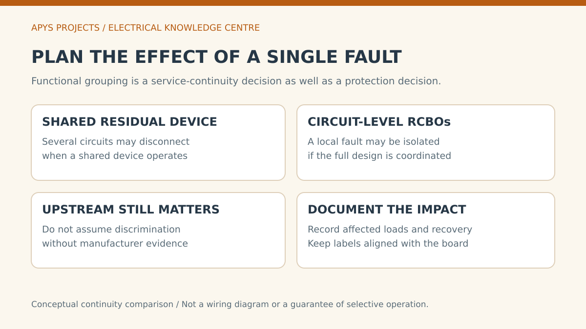
Both arrangements need a complete coordinated design. A shared residual-current device can disconnect several downstream circuits when it operates. Circuit-level RCBOs can support more local fault isolation, but upstream operation and the actual wiring still determine the outage. Eaton’s application guide explains why selective operation between series-connected residual-current devices needs coordination. [5]
Before comparing device costs, record which areas and equipment would lose power together under the proposed circuit grouping. Identify the acceptable interruption for lighting, sockets and network equipment in the actual facility.
Ask the supplier to show a circuit grouping table. Include the normal circuit name, connected equipment, affected area and recovery responsibility. Do not promise selective operation merely because each outgoing circuit has its own RCBO; verify the upstream and downstream coordination.
Existing APYS electrical-work record and trip investigation
The existing Group Surya, Indapur project record documents electrical work by APYS Projects. These two photographs are reused from that record; they show the room and distribution-board arrangement.
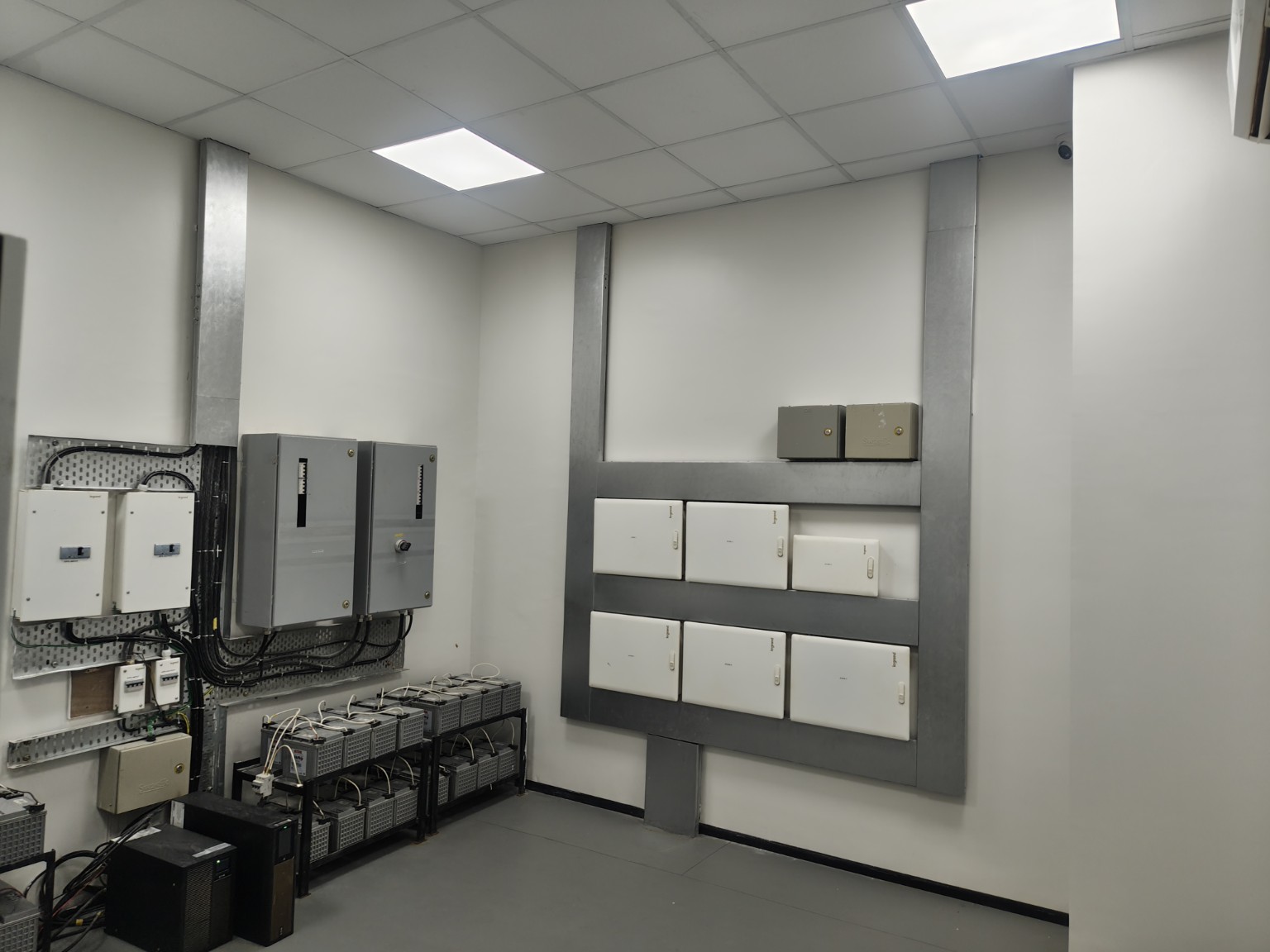
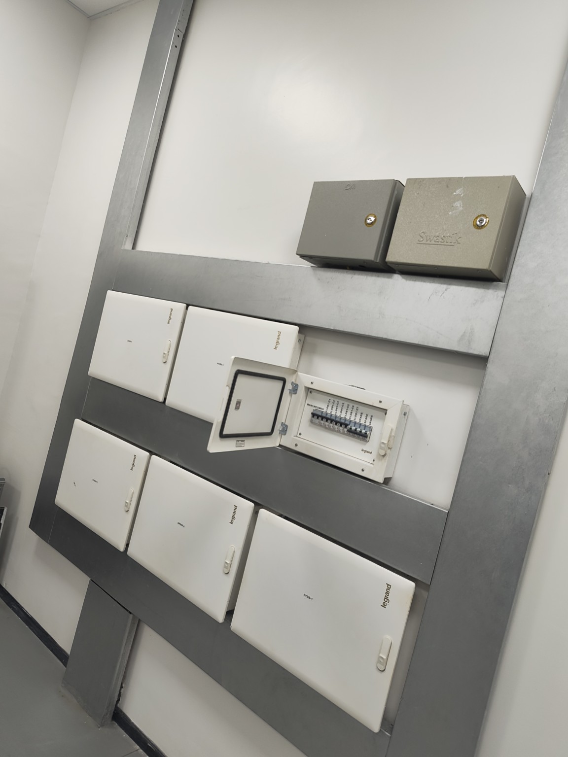
The record does not supply device ratings, a circuit schedule or electrical test measurements. No tripping fault or repair outcome is attributed to this site. For an actual trip complaint, use the following evidence workflow before selecting a remedy:
- Identify the operating device. Record the exact model and any trip indication, without assuming the cause from the handle position alone.
- Map the existing circuits. Confirm that labels correspond to the actual loads and identify any changes since the last drawings.
- Record conditions. Note the loads operating, time, weather, cleaning activity and recently installed equipment.
- Investigate with suitable instruments. A competent person determines the appropriate inspections and measurements.
- Compare remedies. Repair defects first; evaluate grouping or equipment changes against the verified cause and continuity requirement.
- Retest and document. Keep the before-and-after findings and update the schedule.
The investigation may justify replacement, circuit correction or a revised board arrangement. Purchasing components before diagnosis can leave the original fault unresolved.
Repeated tripping: what should be investigated?
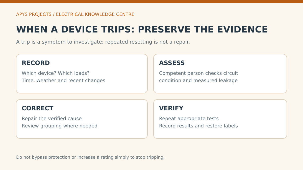
Possible contributors include an actual insulation fault, moisture, an appliance problem, accumulated background leakage, incorrect circuit association or a protection arrangement unsuited to the load. The RCD application guide discusses the importance of application and coordination. [4]
The owner can provide useful observations: does it happen after rain, when one appliance starts, during cleaning, or only when several devices run together? Preserve these details. Do not bypass a device, disconnect protective earthing or repeatedly reset an unresolved fault to keep the office running.
Raising residual sensitivity thresholds or replacing a breaker with a larger rating is not a neutral troubleshooting step. It changes protection. Any alteration must follow a verified engineering decision and the applicable requirements.
What does the test button prove?
A manufacturer’s test button is a functional check under the stated operating conditions. Follow the selected product’s instructions for its use and frequency. It should not be presented as a complete inspection of the circuit, protective conductor or installed system.
A formal handover needs the specified inspection and instrument tests, with readings, circuit references and acceptance limits. Record the device model and test conditions so future maintenance staff can interpret the result. If the expected test action fails, have a competent person investigate rather than assuming a particular internal defect.
What to request in the electrical BOQ
| Scope item | Required clarity |
|---|---|
| Device schedule | Exact manufacturer/model, functions, ratings, poles and quantities |
| Distribution board work | Assembly compatibility, space, termination scope and labels |
| Associated protection | Upstream/downstream coordination and the design basis |
| Circuit corrections | Verified wiring or insulation defects and the agreed repair scope |
| Testing | Methods, acceptance criteria, records and responsibility |
| Shutdown and handover | Work window, controlled restoration, drawings and user briefing |
Use the office electrical load guide to organise the load inventory, then have the protection design developed from the actual circuit conditions. Connected load alone does not determine every device characteristic.
Acceptance and maintenance checklist
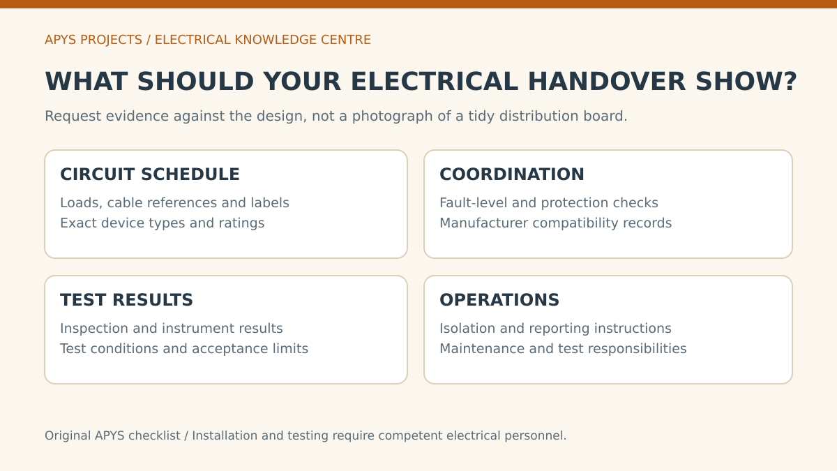
Before sign-off, obtain the final circuit schedule, device data, inspection and test reports, relevant coordination information and clear isolation labels. Review any exceptions and assign an owner for unresolved items.
Agree who performs routine checks, who is called after a trip and how altered circuits are documented. Keep the handover accessible to the facilities team. A protection system is harder to maintain when its evidence is stored only on an installer’s phone.
Frequently asked questions
Can an RCCB replace an MCB?
Not as a like-for-like substitute for overcurrent protection. An RCCB does not contain the integral overload and short-circuit functions of an MCB; the installation needs the appropriate associated protection. [1]
Is an RCBO automatically the right answer for every circuit?
No. It combines useful functions, but the model and arrangement still need to suit the circuit, equipment, fault conditions and coordination requirements.
Will a 30 mA marking tell me the device’s load capacity?
No. Milliamperes in this context describe the residual-current characteristic. The operating-current rating and other relevant ratings must be checked separately.
Should I replace the device whenever it trips?
Investigate first. Operation may indicate that the device is responding to a fault or application condition. Preserve evidence and repair the verified cause.
Discuss the electrical scope with APYS Projects
Contact APYS Projects with the location, circuit schedule, available drawings and the problem you want resolved. Photographs taken from a safe position and a clear history of trips can help define the initial inspection scope; they do not replace site measurements.
Sources and technical references
- Schneider Electric: RCCB and RCBO functions
- Schneider Electric India: MCB vs RCBO
- Eaton RCD Application Guide: Type AC and Type A characteristics
- Eaton: RCD Application Guide
- Eaton RCD Application Guide: selectivity and circuit coordination
- Schneider Electric Electrical Installation Guide: circuit-breaker selection
- Schneider Electric Electrical Installation Guide: RCD technologies
Product capabilities and project requirements must be checked against the selected model, software and applicable installation conditions. Key functional, selection and RCD guidance rechecked: 31 October 2026. This article is not a protection design or engineering sign-off.
Related APYS services and tools: MCB/DB selection planning calculator · Electrical load planning calculator · Electrical service scope