Structured cabling is the permanent nervous system of an office network. Done right, it carries data, voice, Wi-Fi, CCTV, access control, and building systems for 15 to 20 years. Done as a pile of loose patch leads, it becomes the first thing that fails when the floor fills up.
This guide covers how a proper office LAN is designed, built, tested, and handed over.
What Structured Cabling Actually Is
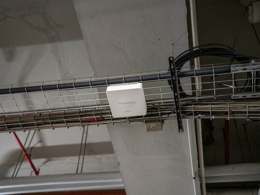
Structured cabling is a standards-based cabling system, not a brand of cable. Every outlet, patch panel, and backbone run follows a fixed topology so any desk, access point, or camera can be patched to any service without pulling a new cable.
A point-to-point job runs one cable from a switch straight to a PC. It is cheap on day one and expensive every time the layout changes. Structured cabling puts a permanent link between a wall outlet and a patch panel in a telecom room. Moves, adds, and changes are done with short patch cords.
The system is defined mainly by ANSI/TIA-568 for commercial practice, ISO/IEC 11801-2 for office premises, and IEEE 802.3 for Ethernet speeds such as 1G, 2.5G, 5G, 10G and PoE.
The cabling does not care whether the traffic is email, a VoIP call, or a 4K camera stream. The design has to.
The Six Subsystems
A complete office system has six parts. Skipping any one of them is how projects look finished and then fail at handover.
- Entrance facility: where the ISP, leased line, or campus fibre enters the building. Demarcation, surge protection, and a short run of single-mode fibre to the main rack live here.
- Equipment room (MDF): the main distribution frame with core switch, firewall, servers, and main fibre patch panels. In a small office this may be the same room as the IDF.
- Backbone cabling: the vertical or campus link between the MDF and each floor closet. Use fibre, not copper, once you leave the floor.
- Telecommunications room (IDF): one per floor, or one per zone if the floor is large. Patch panels, access switches, UPS, and sometimes Wi-Fi controller uplinks live here.
- Horizontal cabling: the permanent runs from the IDF patch panel to each work-area outlet. This is usually 80 to 90 percent of the copper on the job.
- Work area: faceplates, keystones, and the short patch cord to the PC, phone, printer, or thin client.
Topology is a hierarchical star. Workstations star into the IDF. IDFs star into the MDF. No daisy-chains. No bus. No “we will loop this floor later.”
Cable Choice: What to Pull in 2026
For a new office, Cat6A on the horizontal and OM4 fibre on the backbone is the default. Cat6 is still common in India because it is cheaper and easier to pull, but it is the wrong baseline if the fit-out is meant to last.
| Medium | Bandwidth | Practical Office Use | Hard Limit |
|---|---|---|---|
| Cat5e | 100 MHz | Legacy only. Do not specify for new work. | 1G to 100 m |
| Cat6 | 250 MHz | Budget retrofits, short runs, non-critical drops | 1G to 100 m; 10G only to about 37-55 m |
| Cat6A | 500 MHz | New office horizontal standard | 10G to 100 m; PoE++ up to 90 W |
| Cat7 / Cat7A | 600-1000 MHz | Rare in offices. Non-RJ45 hardware, little warranty support | Not a substitute for Cat6A in commercial specs |
| Cat8 | 2000 MHz | Data-centre short links only | 25/40G to 30 m. Not for desk drops |
| OM4 multimode | – | Floor-to-floor backbone | 10G easy; 40/100G on short campus runs |
| OS2 single-mode | – | ISP handoff, long campus, future 100G | Essentially distance-unlimited in an office |
ANSI/TIA-568.2-E, revised in October 2024, recommends Cat6A or higher for new commercial horizontal cabling, and two Cat6A runs per wireless access point. The material premium over Cat6 is typically 15 to 25 percent. Across a 15-year life, that is cheaper than a recable.
Shielding matters. F/UTP Cat6A is a practical office choice where cable trays sit near power. It needs shielded jacks, shielded panels, and bonding to rack earth. U/UTP Cat6A works if pathways are clean and bundles are controlled, but alien crosstalk is the failure mode at 10G.
Use solid copper, 23 AWG, LSZH jacket for commercial ceilings and risers. Reject copper-clad aluminium. It fails PoE, fails certification, and fails within a few years.
Length Rules That Are Not Negotiable
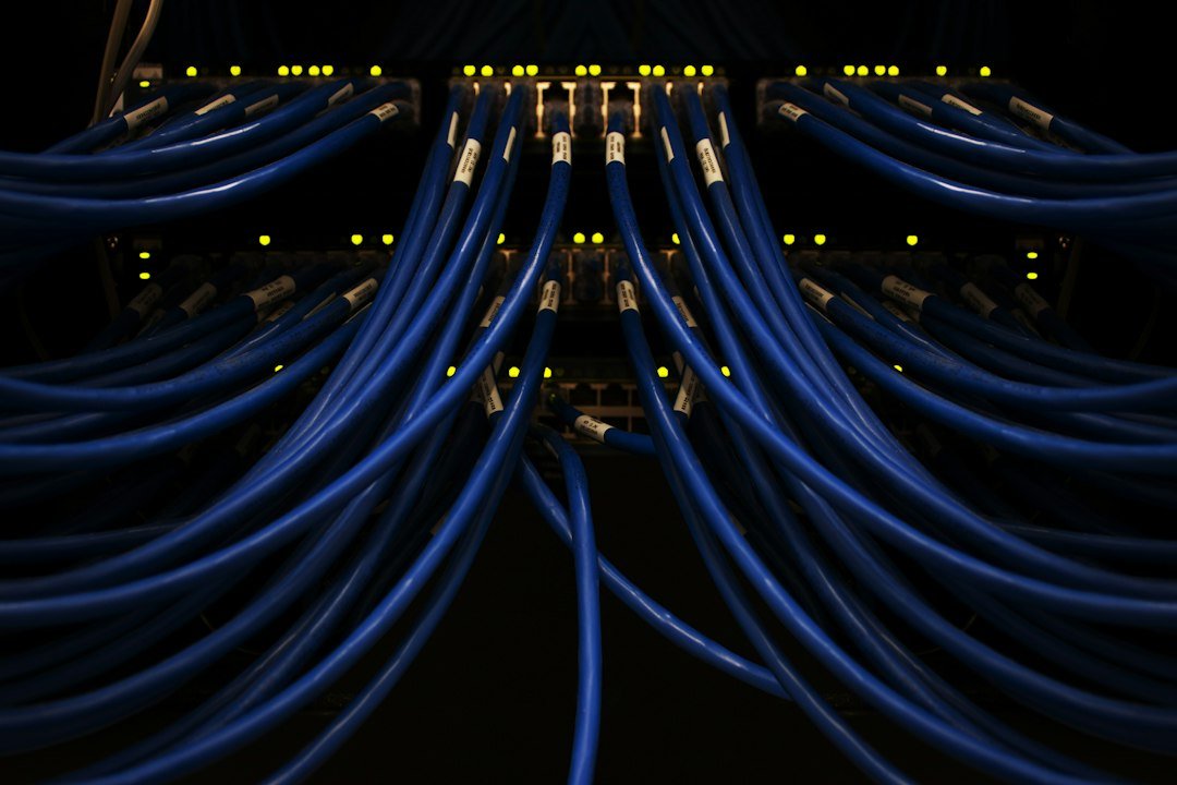
Copper horizontal channel is 100 metres maximum: 90 m permanent link from panel to outlet, plus 10 m patch cords across both ends. The work-area cord is usually capped at 5 m.
That 90 m is the installed path, including service loops and vertical drops, not the straight-line distance on the drawing. A desk that looks 60 m from the closet on plan can be 95 m once the cable goes up, across the tray, and down. If a zone is beyond 90 m, add an IDF. Do not “make it work” with Cat6A and hope.
Fibre backbone has no 90 m problem inside a normal office building. The constraint is the optic. OM4 with 10G SR optics is comfortable for multi-floor risers. Hand the ISP OS2 single-mode so a future 10G or 100G circuit does not force a new riser pull.
How Many Outlets, and Where
A usable office rule before the architect locks the furniture plan:
- 2 copper outlets per workstation: data plus spare, or data plus IP phone
- 2 Cat6A runs per Wi-Fi access point, in the ceiling, not at desk height
- 1 run per CCTV camera position, plus 20 percent spare positions
- Dedicated drops for access control, video door phone, BMS, and meeting-room displays
- Printers, access points, and conference codecs on their own ports, not piggybacked
- 20 to 30 percent spare ports on every patch panel
TIA guidance of two Cat6A runs per access point exists because Wi-Fi 6E and Wi-Fi 7 APs can draw PoE++ and may need multi-gigabit uplinks. One Cat6 drop under a ceiling tile will not carry that cleanly.
Place outlets on the furniture grid, not “one per 10 sq m” as a vague average. Open offices, cabins, meeting rooms, reception, and server niches all have different densities. Confirm the furniture plan before the first pull. Moving a floor box after the screed is poured is a variation, not a snag.
Pathway Design
The cable is only as good as the route.
- Main horizontal: perforated cable tray or wire-mesh basket, sized for 40 percent fill on day one.
- Floor drops: GI conduit or trunking, with draw wire left in spares.
- Riser: separate fibre duct, fire-stopped at every slab.
- Bend radius: at least 4 times the cable diameter during pull, 8 times at final dressed position for Cat6A.
- No staples and no tight nylon ties. Use Velcro. Over-cinched ties crush pairs and fail NEXT.
- Separation from power: 300 mm in parallel runs, or a metal barrier / separate compartment. Cross power at 90 degrees if needed.
- Keep data out of the same conduit as power. Always.
- Service loop: 1 to 3 m at the panel end, and a small loop at the outlet, not a coil stuffed into the box.
- Support every 1.2 to 1.5 m on open tray. Do not let Cat6A hang in a long catenary.
In Indian fit-outs the usual failures are shared power-and-data trunking, trays filled to 100 percent, and fibre pulled through the same sharp basket edge as the copper. Fix the pathway on the drawing, not on site.
Racks, Rooms, and Power
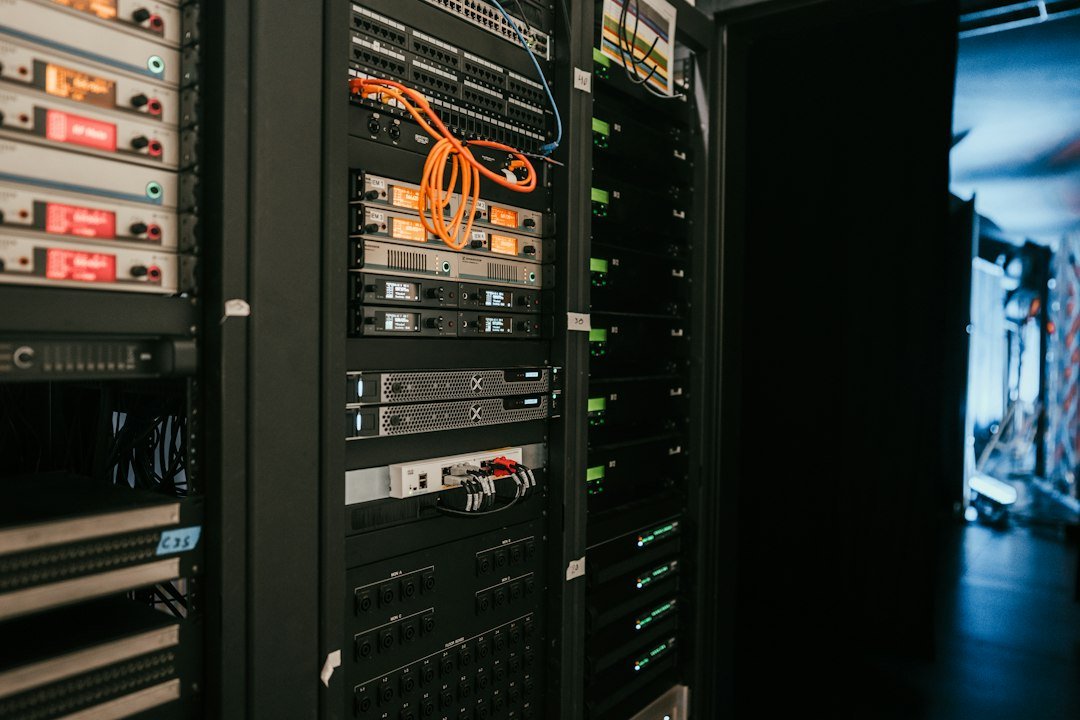
A telecom room is not a store. It needs to be lockable, accessible, cooled, powered, earthed and documented.
- Dedicated room, lockable, not a pantry or AHU space
- 42U rack for a full floor, 22U or 27U for a small office, with 1 m clearance front and rear
- Earthing bar bonded to building earth. Rack, panels, shielded jacks, and tray all land on it
- Independent UPS for switches, sized for PoE load, not just the switch nameplate
- Split AC or at least ventilation. PoE switches and NVRs cook in a closed cabin
- Cable entry from above or via brushed gland panel. No raw cut-outs
- Lighting, spare 16 A socket, and document pocket for the as-built
Label the rack elevation: patch panel U positions, switch U positions, PDU, and fibre tray. The person who maintains this in year four was not on the install team.
Termination Standards
Pick one pinout and use it everywhere. T568B is the usual office choice. T568A is equally valid. Mixing them creates crossover links that fail in non-obvious ways.
- Keep pair twist intact to within 13 mm of the IDC.
- Use the correct keystone for the category. A Cat6 jack on Cat6A cable does not make a Cat6A link.
- Use the same manufacturer system if a 25-year channel warranty is required.
- Fibre should be fusion spliced or factory pre-terminated. Mechanical splices in a riser invite support calls.
- Use dust caps on every unused fibre port.
- Patch cords are stranded and factory-made. Do not crimp office patch leads on site.
Testing and Certification
A cable that “lights the link LED” is not a certified link. Continuity only proves the pairs are connected. It says nothing about crosstalk, return loss, length, or PoE readiness.
Test 100 percent of copper permanent links with a Level IV field tester such as Fluke DSX-8000 class or equivalent, calibrated within 12 months. Set the limit to the specified standard, for example TIA Cat6A Permanent Link, and save every result.
Copper Tests That Matter
- Wiremap: opens, shorts, split pairs, and reversals
- Length
- Insertion loss
- Return loss
- NEXT and PS-NEXT
- ACR-F and PS-ACR-F
- DC loop resistance, critical for PoE
- Alien crosstalk on a sample of bundled Cat6A links
Fibre Tests
- Tier 1: optical loss test set, both wavelengths, both directions
- Tier 2: OTDR trace where splice accountability is required
- OM4 typically at 850 nm and 1300 nm; OS2 at 1310 nm and 1550 nm
- Inspect every connector end-face. A dirty LC connector fails a clean cable
Handover Pack
- Passing certification report for every port, PDF plus native tester file
- Port map and faceplate schedule
- Rack elevations
- Pathway and riser drawings with fire-stop locations
- As-built lengths
- Warranty registration if a branded system was used
No report, no handover. A verbal “all ports are working” is not a document.
Labeling
Label both ends, machine-printed, before the ceiling closes. A simple scheme that survives a facilities team is F03-IDF2-PP05-042: Floor 3, IDF 2, patch panel 5, port 42. The faceplate, patch panel, and test report all use the same ID.
Handwritten marker on the jacket lasts only until the first monsoon and the first AC service.
PoE, Wi-Fi, and the ELV Load
Modern offices are not just PCs. The same horizontal plant feeds Wi-Fi 6/6E/7 access points, IP phones, CCTV cameras, access-control readers, meeting-room panels, displays, sensors and other ELV systems.
- Prefer Cat6A, 23 AWG solid copper, so loop resistance stays inside PoE limits.
- Do not bundle huge PoE groups without checking temperature rise.
- Budget switch power, not just port count. A 48-port PoE switch with 370 W cannot feed 48 high-load cameras.
- Put APs on the reflected ceiling plan with electrical and HVAC drawings so the AP is not behind a beam or AHU.
Design Sequence That Keeps the Project Honest
- Count people, meeting rooms, cameras, APs, and speciality devices. Add growth.
- Place IDFs so no permanent link exceeds 80 m on the drawing, leaving 10 m margin.
- Fix cable category, fibre count, and outlet density in the spec before tender.
- Coordinate trays with electrical, fire, and HVAC. Data loses every clash if it is drawn last.
- Pull, dress, terminate.
- Certify 100 percent.
- Patch, label, and hand over the report with the port map.
For riser fibre, use minimum 12 strands OM4 to each IDF, or 24 if the floor has heavy AP or server traffic. Single-mode in parallel is cheap insurance if the building will take a second ISP or a future campus link.
Mistakes That Show Up After the Client Moves In
- Cat6 specified, then a Wi-Fi 7 AP installed at 70 m that cannot hold stable multi-gigabit speed
- One data point per desk, so IP phone and PC share a small unmanaged switch under the table
- No spare ports, so the CCTV variation has nowhere to land
- CCA cable bought only on price
- Power and data in one trunking with no barrier
- Tight cable ties every 150 mm
- IDF in a wooden cabin with no ventilation, PoE switch thermal-throttling by summer
- Untested links, then a blame loop between data vendor, CCTV vendor, and IT team
- Fibre left unterminated “for later” with no cassette and no test sheet
- Labels that do not match the test report
A Practical Spec You Can Paste Into a Tender
- Horizontal: Cat6A F/UTP, solid copper, 23 AWG, LSZH, 4-pair
- Outlets: dual gang at each workstation, two Cat6A at each AP location, one at each camera
- Permanent link up to 90 m, channel up to 100 m
- Termination: T568B, category-rated keystones and panels, same-system warranty
- Backbone: 12-core or 24-core OM4 as required, LC, fusion or pre-term cassettes; OS2 from entrance facility to MDF
- Test: 100 percent permanent-link certification to TIA Cat6A, Fluke-class tester, reports in handover
- Label: both ends, machine-printed, scheme agreed before pull
- Pathways: 40 percent fill, power separation, fire-stopping at penetrations
- Room: lockable IDF, bonded earth, UPS sized for PoE, ventilation
Cat6 remains acceptable only for a short-life retrofit where every run is well under 50 m and 10G is not required. Write that limit into the spec so it cannot drift.
What “Done” Looks Like
A finished office LAN is boring, which is the point. Every outlet has an ID. Every ID has a passing test page. The AP on the ceiling has two home-run cables, not a loop through a cabin. The riser is fibre. The rack is labelled. A new joiner on Monday is a patch-cord change, not a ceiling opening.
That is the whole job of structured cabling: make the network invisible for the next fifteen years, and make the next change a fifteen-minute task.
APYS Projects Can Help
APYS Projects handles structured cabling, LAN networking, Cat6/Cat6A installation, rack dressing, patch-panel termination, Fluke testing coordination, firewall works, Wi-Fi access point cabling, ELV systems and electrical works for offices, societies, companies and commercial sites.
For structured cabling, LAN networking, Fluke testing, firewall works, ELV or electrical requirements, contact us at Purchase@apysprojects.com.